Compare fabric prepreg and UD tape for composite parts. Learn layup design, common defects like voids, wrinkles and delamination, and ways to prevent them.
Fabric or Unidirectional (UD) Tape? How to Identify Layup Defects: A Comprehensive Guide to Composite Prepreg Selection and Layup Quality
Choosing the right material is only the first step; if the layup is poor, even the most expensive carbon fiber becomes nothing more than scrap.
Introduction
If you work in the R&D of composite structural components, you have likely faced this dilemma—
You have finished the design, but now you’re stuck on selecting a prepreg: Should you use fabric or unidirectional (UD) tape? Some argue that fabric is easier to lay up and conforms better to curved surfaces, while others point out that UD tape offers higher strength and precise directional control. Which one should you choose?
After finally selecting the material and completing the layup, you demold the part—only to find white spots in the corners, wrinkles on the surface, and an ultrasonic C-scan full of red flags, indicating excessive porosity and delamination. The entire batch is scrapped. Where did things go wrong? Was it the material, the mold, or the layup technique?
These two issues—material selection and manufacturing process—may seem unrelated, but they are, in fact, deeply interconnected. The form of the material you choose directly dictates the difficulty of the layup and the risk of specific defects.
In this article, we will systematically explore these topics from two perspectives:
1. Fabric prepregs vs. UD tape prepregs: Their respective characteristics, suitable applications, and layup methods.
2. A comprehensive guide to layup defects: From porosity and delamination to bridging and warping—we break down the root causes of each.
I. Fabric Prepregs vs. UD Tape: A Comparison of Characteristics
To select the right material, one must first understand the fundamental differences between these two forms of prepreg.
1.1 Structural and Mechanical Differences
In unidirectional (UD) tape, fibers are arranged in parallel along a single direction, with no interlacing (weaving) of warp and weft threads.
Advantages: Fibers are free from crimp, allowing for maximum utilization of mechanical properties; longitudinal tensile strength can reach over 90% of the fiber's theoretical strength.
Characteristics: Highly directional; exhibits exceptional performance along the fiber orientation, but very low performance in the transverse (perpendicular) direction.
Disadvantages: Poor drapeability; difficult to conform to complex curved surfaces or structures with double curvature.
Fabric prepregs are composed of interwoven fibers (warp and weft), typically featuring weave patterns such as plain, twill, or satin.
Advantages: Good drapeability; capable of conforming to complex curved surfaces; provides relatively balanced load-bearing capacity in various directions.
Characteristics: Supports loads in both warp and weft directions; mechanical properties are distributed across multiple directions.
Disadvantages: Fiber interlacing (crimp) leads to a reduction in mechanical performance; strength in the warp/weft directions is typically 30%–50% lower than that of unidirectional (UD) tapes of the same grade.
1.2 Selection Comparison Table
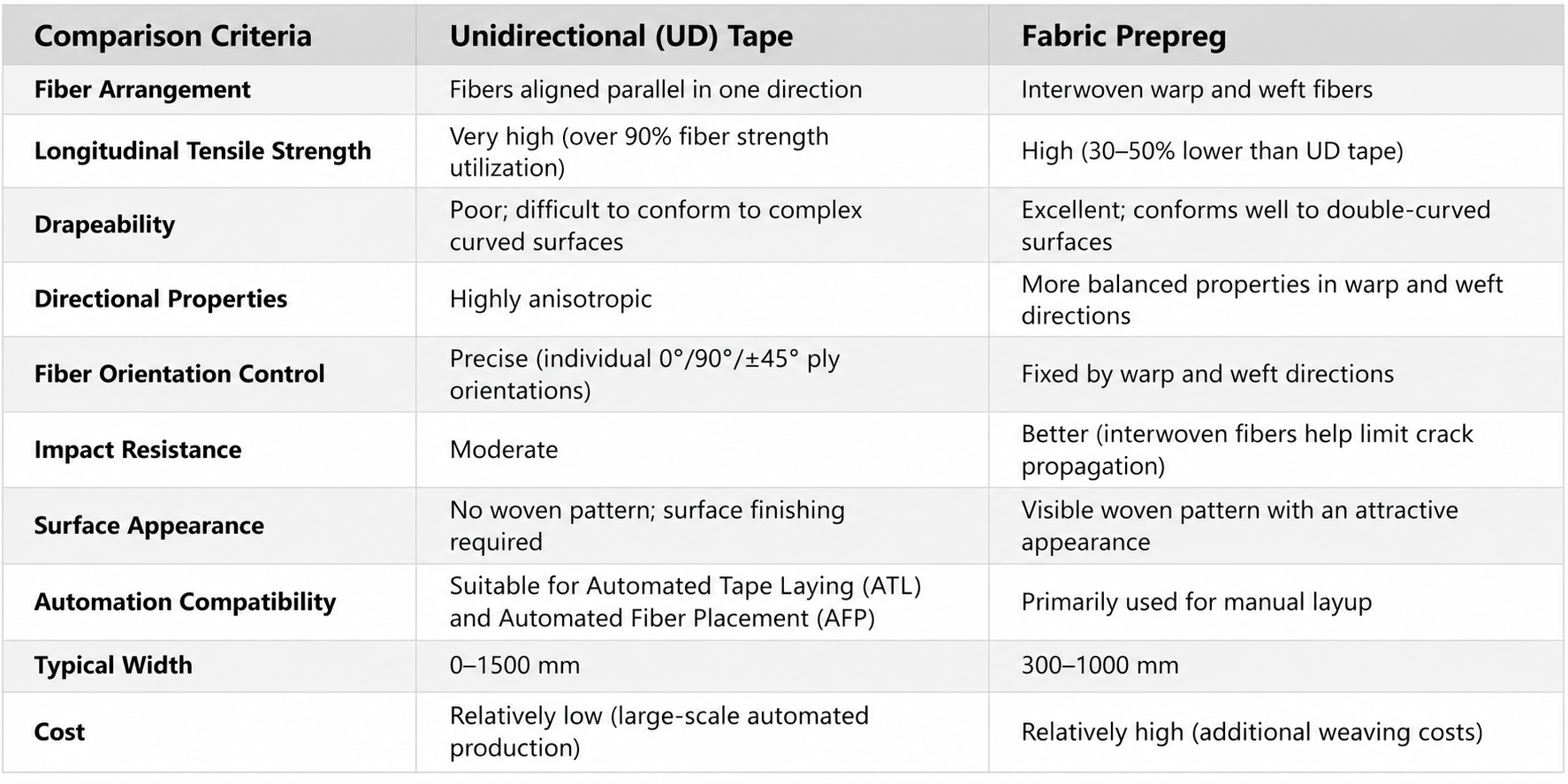
II. Suitable Structural Component Types
Material selection is not a matter of which is "better," but rather which is "more suitable." The following outlines the types of structural components best suited for each of the two categories of prepregs.
2.1 Structural Components Suitable for Unidirectional (UD) Tapes
The core advantage of unidirectional tapes lies in the ability to precisely orient fibers along the direction of principal stress, ensuring that the material's properties are highly aligned with the load paths. Suitable for the following applications:
① Long, straight beam-like components
Aircraft wing spars, fuselage stringers, main spars for wind turbine blades, UAV arms, robotic arm segments, and bicycle tubing.
Characteristics: Clearly defined loading directions, simple geometry, and long spans.
② Primary load-bearing structures
Aircraft wing skins (inner layers), empennage panels, load-bearing frames, pressure vessels, and storage tanks.
Characteristics: Require exceptionally high specific strength and specific stiffness; fiber orientation must be precisely controllable.
③ Regions requiring variable thickness or variable stiffness
Roots of stiffeners, reinforced areas around openings, and load-introduction zones.
Characteristics: Require layer-by-layer addition or removal of material, with precise control over fiber orientation.
④ Automated, high-volume production
Automated Tape Laying (ATL): Large wing surfaces and fuselage barrel sections.
Automated Fiber Placement (AFP): Complex curved surfaces, variable-angle layouts, and areas with multiple openings.
Characteristics: High production volume and stringent requirements for consistent quality.
2.2 Structural components suitable for fabric prepregs
The core advantages of fabric prepregs lie in their excellent drapeability, balanced load-bearing capacity across different directions, and superior impact resistance. Suitable for the following scenarios:
① Components with complex curved surfaces
Nose radomes, wingtip fairings, engine nacelles, automotive exterior parts, and housings for sports equipment.
Characteristics: Double curvature, significant variation in curvature, and complex geometric shapes.
② Aesthetic/surface components
Parts where the carbon fiber weave pattern is visible (e.g., automotive interior trim, consumer electronics housings, or the outer layers of high-end bicycle frames).
Characteristics: Require an aesthetically pleasing weave pattern.
③ Multi-directional load-bearing components
Shear skins (using ±45° fabrics) and face sheets for sandwich structures.
Characteristics: Subject to loads from various directions, requiring balanced load-bearing capacity across multiple axes.
④ Impact-resistant/damage-tolerant components
Surface layers of structures at high risk of impact.
Characteristics: The interlaced structure inhibits crack propagation, offering superior impact resistance compared to unidirectional (UD) tapes.
2.3 Hybrid Layups: Best Practices in Engineering
In engineering practice, it is rare to rely on a single material form; the standard approach is to use a hybrid configuration:
Typical example: High-end carbon fiber bicycle frames—unidirectional (UD) tapes are used in the inner layers, oriented along the axis of the tubes to handle structural loads, while a satin-weave fabric is used for the outer layer to provide both a high-quality aesthetic finish and impact resistance.
2.4 Quick Selection Guide
For straight components subject to unidirectional loads → Prioritize unidirectional (UD) tapes.
For curved shells or components subject to multi-directional loads → Prioritize woven fabrics.
For a balance between strength and aesthetics → Use UD tapes for inner layers and woven fabrics for the outer layer.
III. Principles of Layup Design
Once the materials are selected, the next step is layup design. In essence, layup design addresses four key questions: how many layers to use, what proportion of each orientation to include, the stacking sequence, and how to ensure compatibility with manufacturing processes.
3.1 Layup Orientations and Proportions
Standard orientations commonly used in engineering are 0°, ±45°, and 90°:
No single orientation should account for less than 6%–10% of the total layup; otherwise, the structure will be too weak in that direction, making it susceptible to premature interlaminar failure.
3.2 Principles of Symmetry and Balance
Symmetric: The layup sequence is symmetric with respect to the midplane; for example, [0/45/90/-45]ₛ indicates a mirror-image arrangement on both sides of the midplane.
Balanced: +θ plies and -θ plies appear in pairs, For example, the number of +45° layers is equal to the number of -45° layers.
Why are symmetry and balance required?
Asymmetry → warpage after curing
Asymmetry → Introduction of Bending-Twist Coupling
Even with a symmetric layup, a gradient in the fiber volume fraction across the layers can still cause slight warpage.
Even an angular deviation of just 3° can trigger significant shear deformation. In areas with complex, curved surfaces, the fiber orientation must be adjusted in real time based on the local curvature.
3.3 Rules of Thumb for Stacking Sequences
3.4 Ply Design for Joint Areas
Bolted joint regions have specific requirements for the ply distribution (stacking ratio):
The proportion of plies oriented at ±45° relative to the fastener-loading direction shall be ≥ 40%
0° plies aligned with the fastener-loading direction ≥ 25%
90° ply orientation ≥ 10%
This ensures sufficient shear and bearing strength, while also improving load distribution and mitigating stress concentrations.
IV. Comprehensive Map of Layup Process Defects: Root Cause Analysis
This is the core section of the entire document. Any operational error during the layup process can leave "hidden time bombs" within the final product. Below, we break down common defects and their root causes.
4.1 Voids / Porosity
Phenomenon: Voids appear within the laminate after curing, and ultrasonic C-scan inspection reveals regions of high attenuation. A porosity level exceeding 2% is considered non-compliant.
Impact on Performance: For every 1% increase in void content, interlaminar shear strength decreases by approximately 5%–7%, and compressive strength drops by about 10%.
⚠️ Degassing is the most frequently overlooked step. Many people assume that a final vacuum-bag compaction step is sufficient; however, for thick laminates (>3 mm), air trapped between layers cannot effectively escape to the edges. Intermediate debulking—removing air from the layup—must be performed every 3 to 4 layers.
4.2 Wrinkles / Fiber Waviness
Phenomenon: After curing, fibers deviate from their designed orientation, exhibiting out-of-plane waviness. Cross-sectional metallographic analysis reveals a sinusoidal fiber pattern.
Impact on Performance: Fiber waviness can reduce compressive strength by 20% and interlaminar shear strength by 25%. The severity of the impact increases with the angle of the waviness.
Preventive measures: Ensure the internal fillet radius is at least 3 times the ply thickness; use darts (cuts) to facilitate the draping of complex curved surfaces; and employ a staged debulking process, performing a debulking/degassing step every 3–4 plies.
4.3 Bridging
Phenomenon: Plies, vacuum bags, or auxiliary materials fail to conform to the mold surface at concave corners or depressions, creating a "bridge" across the gap.
Consequences: Resin-rich zones or voids form at the bridging sites, leading to a locally lower fiber volume fraction and a significant reduction in strength in those areas after curing. More critically, the fiber volume fraction gradient at the bridging sites results in varying coefficients of thermal expansion (CTE) through the thickness, which causes "spring-in" deformation.
⚠️ Bridging is a "self-concealing" defect—once covered by subsequent layers, it becomes invisible. It must be monitored and checked in real-time during the layup process.
4.4 Delamination
Phenomenon: Separation between the layers of a laminate; ultrasonic C-scan inspection reveals distinct reflection signals.
Impact on Performance: Delamination is the most dangerous failure mode for composite materials—a "silent killer." BVID (Barely Visible Impact Damage) can reduce compressive strength by more than 50%.
Interlaminar contamination is the most frequently overlooked root cause. Issues such as operators failing to wear gloves, insufficient positive pressure in the cleanroom, or the accidental spraying of mold-release agents onto the layup surface—seemingly "minor" oversights—can ruin an entire batch of products.
4.5 Resin-Rich / Resin-Starved Zones
Phenomenon: Localized areas with an excess of resin (appearing as smooth, raised surfaces) or a deficiency of resin (manifesting as exposed fibers or a whitish appearance).
Impact on Performance: Fiber volume fraction deviates from the design value by more than ±5%, causing mechanical properties to diverge significantly from design expectations.
⚠️ In the zero-resin-bleed process, the design of the process gap is critical. If the gap is too small, resin flows out too rapidly, leading to resin-starved areas and delamination; if the gap is too large, there is insufficient pressure from thermal expansion, resulting in resin-rich areas and voids.
4.6 Gaps & Overlaps
Phenomenon: The presence of gaps or overlaps between adjacent plies or strips; this is particularly common in Automated Fiber Placement (AFP) or Automated Tape Laying (ATL) processes.
Differences in impact between gaps and overlaps:
Gaps are detrimental—they induce stress concentrations, reduce load-transfer capability, and can lead to premature failure.
Overlaps may, to some extent, create a "local reinforcement" effect—enhancing tensile and buckling resistance—but they also increase both thickness and weight.
AFP control standards: Typically, gaps are required to be ≤0.76 mm and overlaps ≤1.27 mm, though specific limits depend on the structural classification.
4.7 Fiber Misalignment / Orientation Deviation
Phenomenon: The actual fiber orientation deviates from the design angle.
Impact on Performance: A 5° deviation can reduce longitudinal tensile strength by approximately 10%–15%. Deviations in ±45° plies have a particularly significant effect on shear modulus.
4.8 Warpage / Spring-in
Phenomenon: The component deviates from its intended design shape after curing and demolding—such as the warping of flat panels or "spring-in" (a change in the included angle) of L-shaped parts.
Preventive Measures:
Design a symmetric and balanced layup.
Control the cooling rate to below 2°C/min.
Cool the part to below 80°C before demolding.
Select mold materials with a Coefficient of Thermal Expansion (CTE) that matches the composite material (e.g., Invar alloy or carbon/epoxy molds).
⚠️ Even with a perfectly symmetric and balanced layup, slight warpage may still occur due to a fiber volume fraction gradient through the thickness (resulting in a higher resin content at the mold-contact surface). This is an inherent characteristic of the prepreg process.
4.9 Incomplete CureObservation: The glass transition temperature (Tg) is below the specified value, and DSC analysis shows a significant residual exotherm.
Impact on performance: When the degree of cure is <90%, the glass transition temperature (Tg) is low, hygrothermal resistance is poor, and mechanical properties deteriorate across the board.
4.10 Surface Defects
V. Quick-Reference Defect Table
To facilitate on-site troubleshooting, all defects and their root causes are summarized below:
VI. Key Process Control Points for Layup
Prevention is better than cure. The following are the key control points throughout the entire layup process:
6.1 Pre-layup
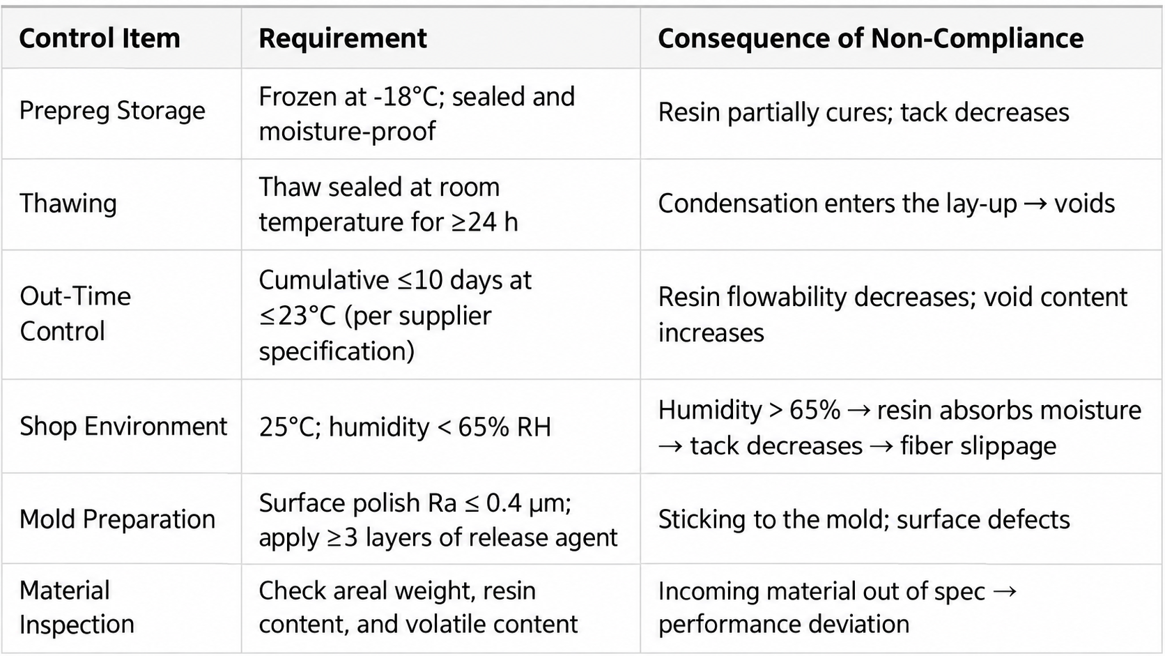
6.2 During layup
6.3 Post-layup / Pre-curing
VII. Key Takeaways
"Whether using unidirectional (UD) tapes or fabrics—the essence of material selection lies in matching the material form to the load paths and geometric features."
"Voids are not created during curing; they are 'planted' during layup. Skipping the debulking (degassing) step might save you 30 minutes, but it could ruin the entire batch."
"Bridging is a 'self-concealing' defect—once covered by subsequent plies, it becomes invisible. It must be detected in real-time during the layup process."
"Delamination doesn't happen suddenly; it stems from 'seeds' of contamination planted between layers. When it comes to cleanliness, there is no such thing as 'good enough'."
"Warpage isn't the mold's fault; it’s a consequence of the laminate design. The price of an asymmetric layup only reveals itself the moment the part is demolded."
"The best process control isn't post-production inspection; it’s ensuring that every step of the process leaves behind a traceable record."
Final Thoughts
70% of the quality of a composite structural component is determined during the layup phase.
Selecting the right material form—whether UD tape or fabric—is the first step; it dictates whether your structure can be manufactured, and how easily. Every operational step during layup—debulking, compaction, corner treatment, and cleanliness management—determines whether the final product is a conforming part or scrap.
Prepregs are "finicky" materials; improper handling of details can significantly degrade final performance. However, by understanding the physical mechanisms behind each type of defect and establishing a systematic process control framework, composite manufacturing can be made stable, controllable, and fully traceable.


